
Spark Erosion and Ship Engine Damage
Spark Erosion and Ship Engine Damage: ports, trade and shipping-market context for US, UK, Canada, Australia, Singapore and European maritime readers.
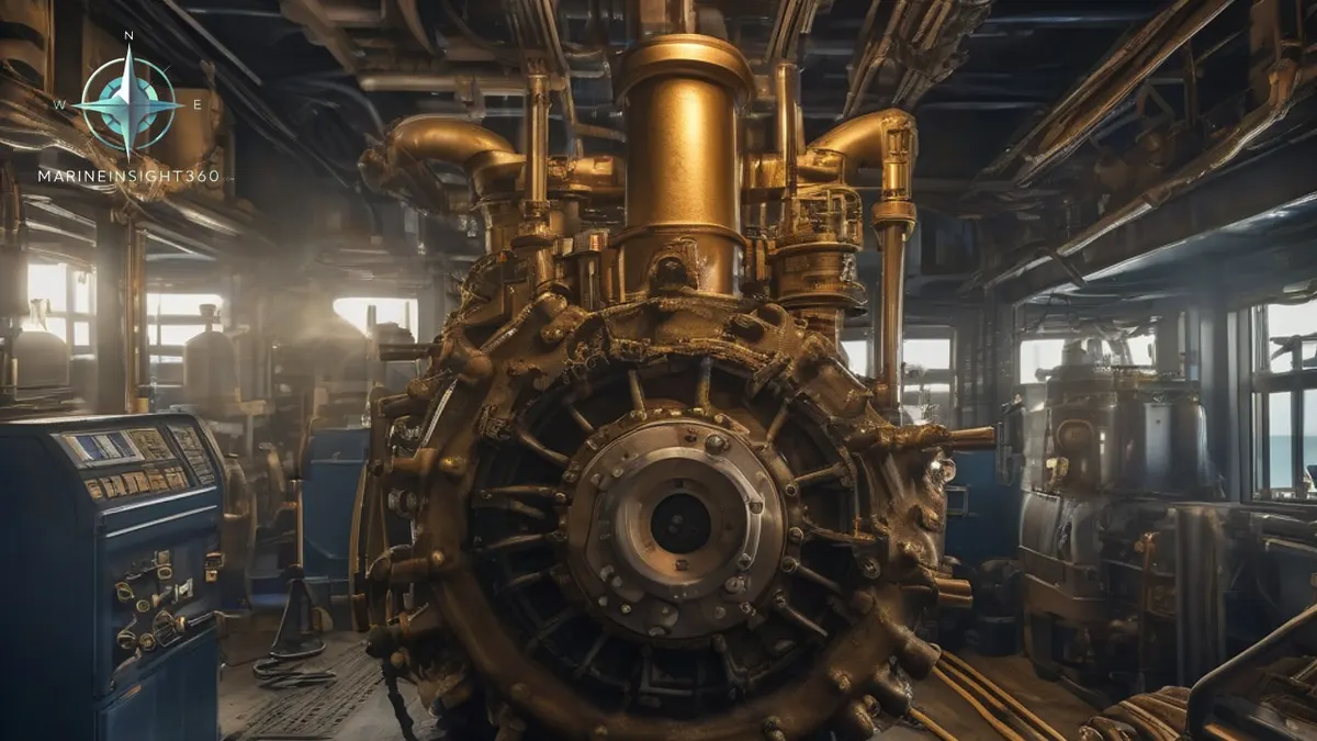
How can Spark Erosion damage a ship's main propulsion engine?
Various automated systems are used on ships to ensure the efficient and smooth operation of machinery. However, machinery failures are common, primarily due to a lack of understanding of these systems by crew members. Therefore, proper installation and maintenance of these systems are crucial to prevent damage.
What is Spark Erosion or electro-discharge machining (EDM)?
Technically, when two dissimilar metals come into contact while energized, sparks propagate and erode the metals at the point of contact, forming a cavity.
On ships, propellers, hulls, crankshafts, bearings, and other components are often made of dissimilar metals. The current generated by cathodic protection systems often flows through these components, creating ideal conditions for EDM.
Even on a steel hull submerged in seawater, a small amount of galvanic current flows through the anode area, causing corrosion and spark erosion.
The Effects of Spark Erosion
To mitigate the effects of galvanic corrosion, especially at the stern of a ship where the propeller is located, a grounded cathodic protection system is often used. The propeller shaft is grounded to ensure circuit continuity and prevent failure.
When the propeller is stationary, the stern tube, propeller shaft, and bearings are in contact. Similarly, the main engine bearings and shaft also contact each other to maintain electrical continuity. When the ship is underway, the propeller shaft is partially electrically insulated due to the propeller's rotation and the presence of a lubricating oil layer. This can also occur on the tail shaft, which uses non-metallic bearings as an insulator.
Ship Engines
The tail propeller has large exposed metal areas, which attract protective cathodic currents. When this current discharges the lubricating oil layer, it generates arcing. This can cause electrostaticcorrosion of the bearings, which is exacerbated if the lubricating oil is contaminated with seawater.
If these effects persist for a long time, spark erosion-induced cavitation can lead to insufficient lubrication and overheating of the main engine bearings. Furthermore, this can cause oil mist formation, emergency engine shutdowns, or, in extreme cases, crankcase explosions.
- Crankcase Explosions – Things You Should Know
- Hezbollah Walkie-Talkies Exploded Across Lebanon
- Exploring 5 Historic Mysteries of the Bermuda Triangle
- Maritime Travel: Exploring the World Via Maritime Travel
- Northlink Explains What Caused Last Month’s Drydock Delays
Causes of Spark Erosion
Major causes of spark erosion problems on ships include:
- Faulty or improperly installed shaft grounding systems.
- Incorrectly adjusted cathodic protection systems.
- Ship Engines,
- Excessive hull plating exacerbates galvanic corrosion of the shaft. Worn slip rings and grounding brushes.
- Poor shaft-to-ground contact.
It is recommended to use two main engine shaft grounding devices: one for grounding and one for connecting a voltmeter to measure the potential difference between the shaft and the hull.
If the potential difference is less than 50 millivolts, the effects of spark erosion are minimal.
What does electrical bearing damage look like when the shell comes out?
Discharge damage does not look like a lubrication failure. A wiped bearing has smeared, displaced white metal and heat discolouration. A bearing eroded by shaft current has a dull, frosted grey surface, and under magnification a field of small round craters where each spark removed metal. The journal opposite it often carries the same matte finish.
It shows first where the oil film is thinnest and the current path shortest: main bearing shells, thrust pads and the aft stern tube bearing. Spectrographic analysis of the used oil picks up the rising white-metal content well before a temperature alarm does, which is why the sample matters more than the gauge here.
Reading the shaft-to-hull millivolt figure
The two-device arrangement described above exists so the reading can be trusted. One brush earths the shaft and carries the current. The second touches the shaft only to measure, so its reading is not corrupted by the volt drop across the working brush. A single brush doing both jobs under-reads the potential it is supposed to reveal.
A climbing figure is usually the brush, not the machinery. Oil mist, salt and carbon dust build a film on the slip ring, contact pressure falls as the brush wears, and resistance rises. Cleaning the ring and renewing the brush is the first action. If the reading stays high, the impressed current system output and its reference cells are the next place to look.
Recommended Reading
Things To Consider When Installing Marine Engine Bedplates
Things To Consider When Installing Marine Engine Bedplates: technology, equipment and fleet context for US, UK, Canada, Australia, Singapore and...
What is the World's Most Powerful Ship Engine?
What is the World's Most Powerful Ship Engine?: ports, trade and shipping-market context for US, UK, Canada, Australia, Singapore and European maritime...
Marine Steam Engine - How it Works?
Marine Steam Engine - How it Works?: technology, equipment and fleet context for US, UK, Canada, Australia, Singapore and European maritime readers.