
What Is the Keel in a Ship? Types, Function and Keel Laying
The keel is the backbone of a ship, running along the centerline of the bottom. Flat plate, bar and duct keels compared, plus why the keel laying date matters.
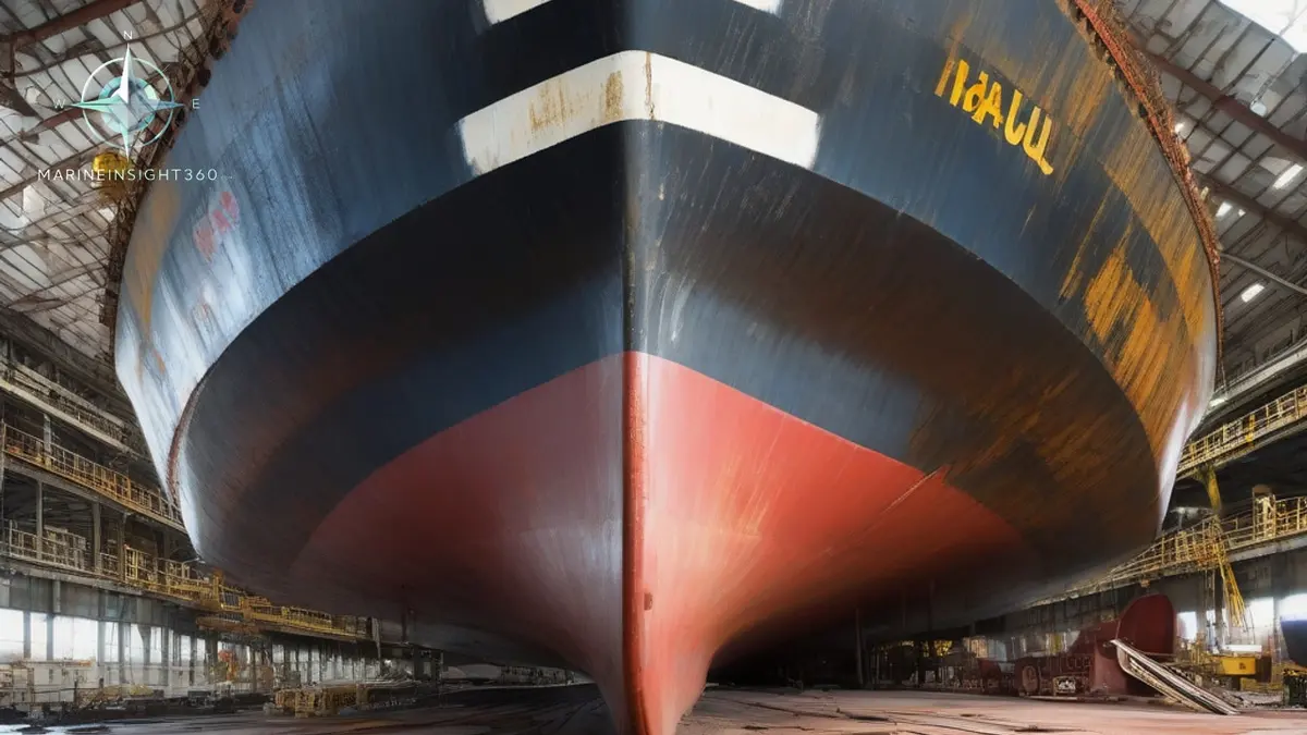
The keel is the main longitudinal structural member of a hull. It runs along the centerline of the bottom, from the stem forward to the stern frame aft. What is keel in ship construction actually for? It carries longitudinal bending loads, ties the transverse structure together, and resists the concentrated loads of docking and grounding. It also gives the shipbuilder the datum line for setting out the rest of the structure.
On almost every modern merchant ship the keel is a thickened centerline strake of bottom plating, not a separate bar. Class rules from ABS, Lloyd's Register and DNV set its scantlings.
That structural role explains the language around it. A ship is said to be laid down when its keel is laid. The hull girder strength calculations that classification societies check are built around the keel and the longitudinal members attached to it. Damage at the keel is treated far more seriously than equivalent damage in the side shell.
The three types of keel and where each is used
Flat plate keel
The flat plate keel is the standard arrangement for ocean-going merchant vessels. It is a plate strake along the centerline, thicker than the adjoining bottom plating. With a vertical center girder and a horizontal rider plate above it, the arrangement forms an I-section. The extra thickness is carried over the midship region where bending moments are highest, and it may taper toward the ends of the ship. The strakes immediately outboard of the keel plate are the garboard strakes.
Bar keel
A bar keel is a solid rectangular bar fitted along the centerline, projecting below the bottom plating, with a depth typically several times its width. It is found on trawlers, tugs, small coasters and older craft. Because the bar sits below the hull, it gives some protection in grounding and improves directional stability. The connection between the keel and the floors is indirect, though, so it does not deliver the strength a large hull needs.
Larger ships moved to flat plate keels for that reason.
Duct keel
A duct keel is used in double bottom ships. Two longitudinal girders sit a modest distance apart on either side of the centerline, closed by plating to form a watertight box inside the double bottom. The box normally runs from the collision bulkhead aft to the forward engine room bulkhead. It carries ballast, bilge and fuel piping through the cargo area without running those lines through the tanks themselves.
That protects the cargo from contamination and gives access for inspection and repair. On tankers, the arrangement also keeps piping out of cargo spaces.
What a keel is not
Two other structures share the word and cause confusion. Bilge keels are the long fins welded to the turn of the bilge on each side of the hull. They damp rolling by generating drag and vortices as the ship rolls, and they have nothing to do with longitudinal strength. A sailing yacht keel is a ballasted fin projecting below the hull that provides righting moment and resists leeway.
Both are keels by name; only the centerline structure described above is the hull's backbone.
Why the keel laying date carries legal weight
Keel laying is not only a ceremony. In IMO conventions, a ship is generally treated as being built to the standards in force at the date its keel is laid or it is at a similar stage of construction. That stage has its own definition. Construction identifiable with a specific ship must have begun, and assembly must have reached at least 50 tonnes, or one per cent of the estimated mass of all structural material, whichever is less.
The practical consequence is that a single date decides which rules a ship carries for its whole life. That covers which SOLAS amendments apply, which MARPOL construction requirements bind it, and which class rule edition the structure was designed to. Owners ordering tonnage around a regulatory cut-off pay close attention to that date. Buyers of second-hand ships check it before assuming what a vessel is required to have on board.
Keel condition, docking and grounding
Every dry docking puts the ship's entire weight onto the keel through a line of keel blocks. The docking plan therefore shows block positions set clear of tanks, sea chests, sounding pipes and other bottom penetrations. A misplaced block concentrates load in the wrong place and can set up local deformation.
These points come up repeatedly in survey and drydock work.
- Keel plate thickness is measured by ultrasonic gauging at renewal surveys, and class sets allowable diminution limits for the plating and the associated girders.
- Grounding damage is assessed along the keel line first, because set-up or buckling of the center girder affects the whole hull girder rather than one compartment.
- Duct keel access covers and the ventilation of the duct are checked before entry. It is an enclosed space, with a real risk of oxygen deficiency and gas accumulation.
- Coating breakdown along the keel and garboard strakes accelerates once blocks are removed and bare steel is exposed to seawater and stray currents.
- Hogging and sagging measured through draft readings reflect how the hull girder, and therefore the keel structure, is being loaded by the cargo distribution.
What this means for the deck and engineering team
Loading decisions are keel decisions. Shear force and bending moment limits in the loading computer keep the hull girder within its designed stress range. The keel is the primary flange of that girder in the bottom. Loading a bulk carrier in alternate holds without checking the computer output is the fastest route to overstressing that structure.
For the structural background behind stability and stress limits, look to the naval architecture material in the Marine Insight 360 Knowledge Base. It sets out how hull girder loads are calculated and where the margins sit.
Sources and further reading
- Importance of a Ship's Keel and Types of Keel
- What Is a Keel on Ships and Boats? Types of Keel Explained
What to read next
Recommended Reading
Inside the Arleigh Burke Destroyer: What an 80th Keel Laying Represents
The US Navy lays the keel of its 80th Arleigh Burke destroyer. What a DDG-51 is, how Flight III differs, and how merchant crews should handle one at sea.

Importance of Laying a Ship's Keel
Importance of Laying a Ship's Keel: technology, equipment and fleet context for US, UK, Canada, Australia, Singapore and European maritime readers.
Cadeler 20MW Wind Turbine Installation Vessel Keel Laid: Inside a Next-Generation WTIV
The keel laying of Cadeler's 20MW wind turbine installation vessel explained: crane capacity, deck area, jack-up limits and what the milestone means.