
Understanding Rectifiers and Their Circuits on Ships
Understanding Rectifiers and Their Circuits on Ships: technology, equipment and fleet context for US, UK, Canada, Australia, Singapore and European...
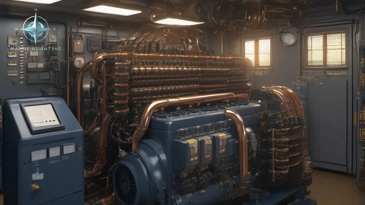
Rectifiers on ships are diode circuits that change the vessel's AC supply into the DC needed by battery chargers, control and automation panels, alarms, instrumentation and communication equipment.
Rectifiers on ships convert alternating current (AC) into direct current (DC) for equipment that cannot run directly from the ship's AC supply. They are used in battery chargers, control circuits, automation panels, alarms, instrumentation, communication equipment and many electronic systems. A small rectifier fault can therefore affect much more than one component.
This guide explains how rectifiers work, where they are used onboard and what engineers and trainees should check when a DC circuit behaves incorrectly.
What a rectifier does
A rectifier uses semiconductor diodes to allow current to flow in one direction. In a simple circuit, this changes AC into pulsating DC. In practical shipboard equipment, smoothing capacitors, filters, regulators and protection devices are often added so that the output becomes suitable for electronic loads.
The rectifier does not create power on its own. It changes the form of electrical supply. Most ships generate AC power, while many control and backup systems need DC voltage. Rectifiers connect those two requirements.
Common rectifier arrangements
A half-wave rectifier uses one diode and conducts during only part of the AC cycle. It is simple but produces more ripple and is not common for important shipboard loads. A full-wave rectifier uses both halves of the AC cycle and produces a smoother output.
The bridge rectifier is widely used because four diodes can provide full-wave rectification without needing a centre-tapped transformer. Three-phase rectifier arrangements are used where higher power and smoother DC output are required, such as battery charging systems or larger control supplies.
Where rectifiers are used onboard
Rectifiers may be found in emergency battery chargers, navigation and communication power supplies, alarm monitoring systems, automation panels, generator excitation systems, cathodic protection equipment and variable speed drive control sections. Some circuits support equipment linked to rpm control, kW load sharing or machinery protection.
Because rectifiers often sit inside larger panels, the fault may first appear as a low DC voltage alarm, repeated fuse failure, noisy relay operation, unstable display or battery not charging properly.
Symptoms of rectifier problems
Common signs include low output voltage, high ripple, overheating, burnt smell, discoloured terminals, blown fuses, tripped breakers, swollen capacitors or unstable equipment. A failed diode may create open circuit, short circuit or reduced output depending on the arrangement.
Engineers should avoid replacing parts blindly. Check the incoming AC supply, transformer output, fuse continuity, diode condition, connections, load current and ventilation. A downstream fault can overload a healthy rectifier, so the connected load also needs attention.
Safe troubleshooting basics
Electrical troubleshooting should be done only by competent personnel following the vessel's isolation and permit procedures. Capacitors can hold charge after power is removed, and control panels may contain more than one supply. Always verify isolation with a suitable meter before touching conductors.
When testing diodes, use the diode function of a multimeter where appropriate and compare readings in forward and reverse directions. For live measurements, record AC input, DC output and any ripple checks according to the maker's manual and company procedure.
Common mistakes
- Replacing a rectifier without checking whether the connected load caused the failure.
- Ignoring cooling fans, dust and blocked ventilation around charger panels.
- Assuming low DC voltage always means a diode fault.
- Working inside a panel before stored energy has been discharged and verified.
What one failed diode looks like on the meter
A three-phase bridge conducts six times per supply cycle, so its ripple sits at six times the supply frequency: 360 Hz on a 60 Hz system, 300 Hz on a 50 Hz one. A single-phase full-wave bridge ripples at twice the supply frequency. Knowing which figure to expect turns a ripple reading into a diagnosis rather than an observation.
Lose one diode in a three-phase bridge and the output does not disappear. The mean DC voltage falls a little, the ripple rises sharply and a component at the supply frequency appears in it. The remaining diodes and the transformer windings then carry more current than they were sized for, so the second failure follows the first.
The symptom reaching the engineer is rarely a dead panel. It is a battery that charges but never quite reaches float voltage, a transformer running warmer than its neighbours, or an electronic load that resets under peak demand while the DC voltmeter still reads roughly normal.
Why the emergency battery charger is the one that gets surveyed
SOLAS Chapter II-1 sets the endurance an emergency source of power has to deliver: 18 hours on a cargo ship and 36 hours on a passenger ship. Where a transitional source is required, batteries carry the emergency lighting and essential services for the first 30 minutes. A rectifier quietly undercharging those batteries removes that margin, and nothing on the panel says so.
Float and boost are different working points, not settings to be left alone. Lead-acid cells sit at roughly 2.25 volts per cell on float and around 2.4 volts per cell on an equalising charge. A charger stuck in boost gasses the electrolyte and dries the cells. One stuck low leaves the bank undercharged, and that shows up as a failed discharge test at survey rather than as an alarm at sea.
So the emergency switchboard charger deserves its own place in the planned maintenance system: specific gravity or terminal voltage readings, a load test on the schedule the flag state accepts, and a note of charger output at both float and boost. Port state control asks to see that record, not the rectifier.
Recommended Reading

How Are Electronic Circuits Installed On Ships?
How Are Electronic Circuits Installed On Ships?: technology, equipment and fleet context for US, UK, Canada, Australia, Singapore and European maritime...

Iran retaliates with missiles and drones, defying Trump’s warning
Learn iran with practical maritime context, safety checks, operational guidance and related resources for global shipping readers.

Hapag-Lloyd Invests in APM Terminals Rotterdam to Drive Growth
Hapag‑Lloyd’s new stake in APM Terminals Rotterdam aims to expand capacity, improve hinterland links and enhance crew efficiency in Europe’s busiest port.